Resistor networks and arrays are a useful item in the design engineer’s component kit. These networks combine from three to over twenty resistors in a single IC-like package. They increase design and layout options and can enhance performance when making the transition from the schematic circuit diagram to actual layout and bill of materials (BOM). Arrays are simply a subset of networks, in which all elements have the same ohmic value.
The network is especially beneficial when the design needs multiple pull-up, line-termination, or gain-setting resistors. Among the strongest cases for using such a network is the inherent matching it offers with respect to changes in resistance due to temperature shifts, a consequence of the common thermal substrate. This is an important consideration in many sensor- and interface-related applications where balanced or ratiometric circuits facilitate cancellation of drift-related errors. It’s important to remember that, whilst discrete resistors can provide close TCR matching, through selection or tight absolute TCR, they can never offer matching of actual element temperatures.
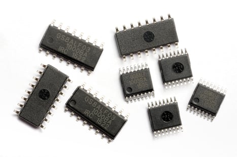
This does not mean that all such networks are necessarily prone to large drift: for example, the QSOP-C and SOIC-C high-density resistor networks from TT Electronics combine high precision with stability and reliability, Figure 1. They have a ceramic substrate, relatively large feature size, and self-passivating tantalum nitride (TaN) film technology for an inherently moisture-proof film system. With ±5ppm/°C TCR (temperature coefficient of resistance) tracking, and ±0.05% ratio tolerance, these networks can ease some of the pressure on a project’s error budget.
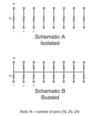
Networks also save precious PC board “real estate” since a multi-resistor package often takes up less space than individual resistors occupy. The QSOP-C series has 0.025” lead spacing, and the standard JEDEC 24-pin version measures just 8.66 × 6.02 mm including leads. They may also reduce needed PC traces if some or all of the resistors have a common connection, Figure 2. Networks also support a routing discipline which enables a cleaner, more logical layout arrangement
On the production side, using a network results in a shorter BOM which, in turn, results in fewer items to order, stock, or risk being unavailable. Networks also simplify the actual production process as there are fewer component reels to use, and they speed assembly since a single pick-and-place step is need to put the resistors on the board, rather than multiple steps.
Nonetheless, it is not a good idea to automatically assume that a resistor network is the best way to go, as they do have some other considerations which must be evaluated. First, by placing all resistors in a single package and thus at a single location, they may actually require longer PC-board traces. Besides adding to board crowding and layout challenges, these longer traces may increase noise pickup and adversely affect signal integrity.
Whilst custom networks offer the ultimate design flexibility for passive integration, arrays are easier to source off the shelf. Clearly, though, all resistors having the same value, can be a design constraint. However, standard networks are available with different, commonly needed values, or with internal configurations for commonly used functions (such as a ratiometric voltage divider) which can simplify a layout. Alternatively, it may make sense in some cases to externally join resistor elements of array in series or parallel to raise or lower the resistance, respectively. For example four elements of an array can be used to create a 3:1 or a 4:1 resistance ratio.
There are two other factors to keep in mind when deciding to use a resistor network: thermal impact and crosstalk. Although the network package may be operating within its dissipation ratings, it does concentrate this dissipation in a small, localized area (which is not the case if spreading individual resistors around the board). If this location is in a thermal “shadow” zone with marginal airflow (whether forced or natural convection), some resistor-network thermal derating may be needed.
Finally, network users have a valid concern with crosstalk since, unlike individual discrete devices, the multiple resistors do share a common substrate. While this is a potential issue with networks using silicon substrates, the ceramic-based element used for the TT Electronics QSOP-C and SOIC-C networks features larger feature sizes and therefore lower crosstalk.
In short: resistor networks offer an alternative with multiple potential benefits to both circuit-design and board-layout challenges, but they also have some attributes which must be considered before making the final BOM decision.
Find out more about all our resistors here.