Abstract
This article revisits the fundamentals of high-voltage resistive division and explores why traditional methods struggle to reconcile high voltage with high precision. It then introduces a newer cascaded, balanced design technique that offers a step change in performance without resorting to proprietary thick-film materials or costly matching processes.
The Challenge of High-Voltage Precision
At its simplest, a resistive voltage divider consists of two resistors in series, with the output taken from their junction (Figure 1). The division ratio is determined by the ratio of the resistor values rather than their absolute resistance. For low voltages and modest ratios, this approach works extremely well and can achieve excellent accuracy using thin-film or foil resistor technologies.
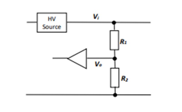
FIGURE 1
High-voltage applications, however, impose a different set of constraints. Continuous operating voltages in the kilovolt range require thick-film resistor technology for its insulation strength, surge tolerance, and environmental robustness. Unfortunately, thick-film resistors exhibit higher absolute tolerance, larger temperature coefficients of resistance (TCR), and more pronounced voltage coefficients of resistance (VCR) than their thin-film counterparts.
At the same time, high-voltage dividers typically require large resistance ratios, which can often range from hundreds to thousands to one. Achieving these ratios forces designers to combine very different resistor geometries and resistivities, making it increasingly difficult to ensure that the two elements track one another over temperature, voltage, frequency, and time.
Why Conventional Dividers Drift
In a traditional two-element integrated divider, the high-voltage resistor must be realised as a long resistive track to accumulate sufficient resistance, while the low-voltage resistor occupies a comparatively compact area. This difference in geometry leads to unequal electric field distributions, parasitic capacitances, and thermal behaviour.
To continue the discussion of voltage dividers and prepare for the alternative design method to be described, two new terms need to be proposed.
Temperature Coefficient of Voltage Ratio (TCVR) is the reversible change in the voltage ratio due to changes in temperature and is expressed in ppm/K. In a conventional divider design, the tracking TCR is used to characterise this parameter.
Voltage Coefficient of Voltage Ratio (VCVR) is the reversible change in the voltage ratio due to changes in input voltage and is expressed in ppm/V. In a conventional divider design, the tracking VCR is used to characterise this parameter. Note that, unlike the VCR of a single resistor, which is always negative, VCVR may be positive or negative.
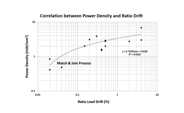
FIGURE 2
In-house datasheet analysis was performed of the major suppliers of thick film high-voltage dividers, paying particular attention to the three key aspects of precision: TCVR, VCVR, and life drift. It was found that dividers with conventional design and process are the most common and offer precision up to 10ppm/K, 0.2ppm/V, and life drift of 0.3%, although 25ppm/K, 1ppm/V, and 0.5% are more typical values. The direct writing process for thick-film application delivers a fourfold improvement in VCVR, whilst the matching strategy offers nearly a decade of improvement in both TCVR and VCVR.
Because the two resistive elements respond differently to temperature, applied voltage, and ageing, the divider’s voltage ratio can change even when absolute resistance changes remain within specification. Manufacturers mitigate these effects through tighter material control, conservative derating, or by matching and pairing resistors – sometimes even bonding separate substrates together.
While effective, these strategies add cost, complexity, and yield risk, restricting the highest-performance dividers to niche applications.
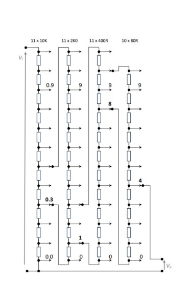
FIGURE 3
The Limits of Incremental Optimisation
Further analysis highlights the strong relationship between power density and ratio drift in thick-film dividers (Figure 2). Reducing drift often relies on operating components well below their rated power and voltage, increasing size or limiting usable range.
This underscores a key point: beyond a certain level, improvements in performance cannot be achieved solely through material and process refinement. The divider topology itself becomes the limiting factor.
A Different Way to Divide Voltage
An alternative philosophy can be found in laboratory instrumentation, where ultra-precise voltage division has long been achieved using the Kelvin-Varley divider. This architecture uses multiple identical resistor elements arranged in balanced stages and cascaded to achieve high ratios with exceptional linearity and stability.
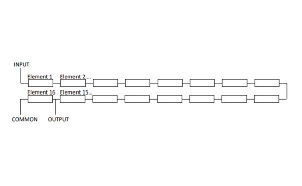
FIGURE 4
While traditional Kelvin-Varley dividers are switchable, low-voltage instruments, the underlying principles of balance and cascading can be adapted for fixed-ratio, high-voltage applications.
Cascaded Balanced Divider Architecture
The cascaded balanced divider replaces the single large ratio of a conventional divider with two or more moderate-ratio stages. Each stage consists of multiple identical resistor elements, with one element forming the low-voltage leg and the remaining elements forming the high-voltage leg (Figure 4).
When stages are cascaded (Figure 5), the overall division ratio becomes approximately the product of the individual stage ratios, provided that inter-stage loading is kept sufficiently low.
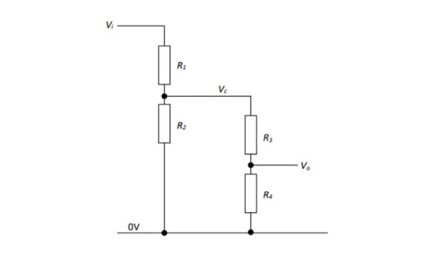
FIGURE 5
Because all elements within a stage are geometrically and materially identical, their TCR, VCR, and ageing behaviour are inherently matched. The voltage ratio of each stage, therefore, remains stable, even if the absolute resistance values drift.
Sensitivity and Error Propagation
Analytical treatment of the cascaded 3-stage divider architecture shows that errors within each stage add statistically, rather than linearly, to the overall ratio error. More importantly, mismatches between stages have a greatly reduced effect provided the impedance hierarchy between stages is maintained. This behaviour is confirmed by PartSim circuit simulation results, where deliberate mismatches introduced into intermediate stages produce only minor changes in overall ratio (Figure 6).
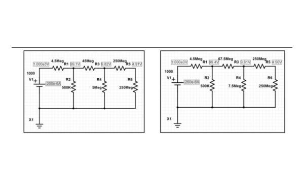
FIGURE 6
In practice, this means that precision is dominated by in-stage matching, which is controlled by design, rather than inter-stage matching, which can be allowed to vary.
Layout and Manufacturability
The cascaded balanced approach does not rely on specialised materials or direct-write processes. Instead, it leverages careful layout and symmetry using standard thick-film manufacturing techniques.
An example layout for a multi-stage divider illustrates how matched elements can be arranged side by side, with consistent conductor geometry and controlled spacing (Figure 7).
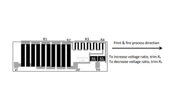
FIGURE 7
Alternative layouts can preserve compatibility with conventional three-terminal divider pinouts (Figure 8).
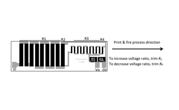
FIGURE 8
Coarse adjustment of input impedance can be achieved through selective disconnection of parallel elements rather than partial trimming, avoiding imbalance in the high-voltage stage (Figure 9). Fine ratio adjustment is best confined to low-voltage stages where electrical and thermal stress is minimal.
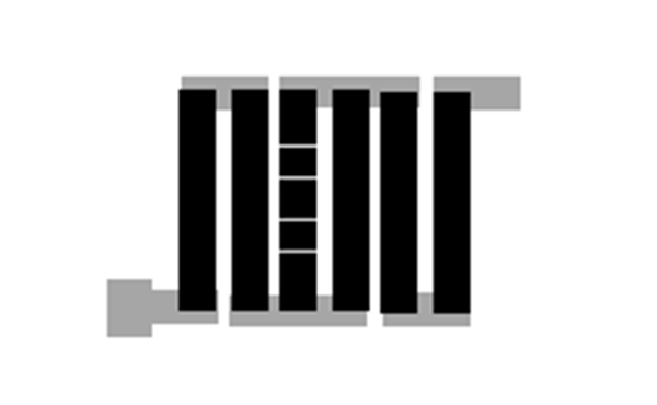
FIGURE 9
Measured Performance
Prototype devices built using this architecture demonstrate the benefits predicted by analysis. A test layout and finished sample are shown in Figure 10.
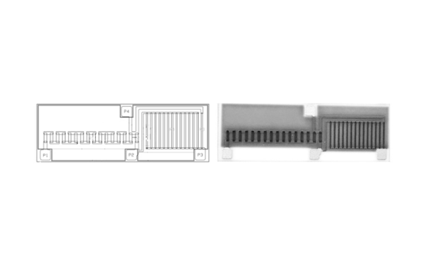
FIGURE 10
Temperature coefficients of voltage ratio were found to be significantly lower than the absolute TCR of the resistive material, confirming the effectiveness of the balanced design. Voltage linearity measurements show consistent behaviour across a wide operating range (Figure 11), approaching the performance of the best matched-element dividers.
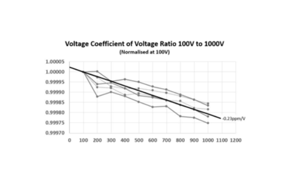
FIGURE 11
When to Consider a Cascaded Approach This architecture is not intended to replace all conventional dividers. Simpler applications with modest precision requirements may still favour traditional designs. However, cascaded, balanced dividers are particularly attractive where:
- High voltage and high precision must coexist
- Long-term ratio stability is critical
- Thick-film technology is required for environmental or surge reasons
- Cost or volume precludes extensive component matching
Typical examples include EV battery monitoring, medical energy delivery systems, and industrial high voltage sensing with digital calibration.
Conclusion
High-voltage resistive dividers have traditionally been optimised through incremental improvements in materials and process control. By revisiting the divider at the schematic level and adopting a cascaded, balanced architecture, it is possible to achieve a step change in precision and stability using conventional manufacturing methods.
The cascaded balanced divider demonstrates that high performance does not have to come at the expense of cost or manufacturability. For designers operating at the intersection of high voltage, accuracy, and reliability, it offers a compelling new design direction.